Clutch Diagram for a Manual Transmission: A Comprehensive Guide

Embark on a journey into the heart of manual transmissions! This guide unveils the secrets of the clutch system, a vital component for gear shifting. We will explore its components and functionality, guided by a comprehensive clutch diagram.
The clutch in a manual transmission vehicle is a critical component, acting as the intermediary between the engine and the gearbox. Its primary function is to engage and disengage the engine’s power from the transmission, allowing the driver to smoothly shift gears. Understanding the clutch is essential for anyone who drives a manual car or works on vehicles.
The clutch is located between the engine and the transmission. When the clutch is engaged, the engine’s power is transferred to the transmission, which then drives the wheels. When the clutch is disengaged, the engine is disconnected from the transmission, allowing the driver to shift gears without damaging the drivetrain.

The clutch consists of several key components, including the flywheel, clutch disc, pressure plate, and release bearing. These components work together to transmit power from the engine to the transmission. A clutch diagram is a visual representation of these parts and their relationship to one another. Examining such a diagram is a great way to understand the system.
Purpose of a Clutch in a Manual Transmission
The clutch serves a crucial role in a manual transmission system. Its primary purpose is to seamlessly connect and disconnect the engine from the transmission. This engagement and disengagement are necessary for several key functions within the vehicle’s operation. Without the clutch, shifting gears in a manual transmission would be impossible without causing significant damage to the drivetrain.
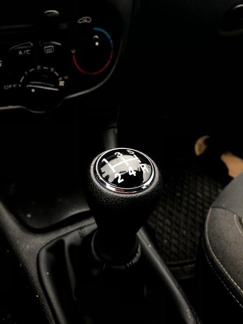
During gear changes, the clutch allows the driver to temporarily interrupt the power flow from the engine, enabling the selection of a different gear ratio. This prevents the gears from grinding against each other and ensures a smooth transition between gears. Furthermore, the clutch is essential for starting the vehicle from a standstill. By disengaging the engine from the wheels, the clutch prevents the engine from stalling when the vehicle is stationary.
In essence, the clutch acts as a mediator between the engine’s constant rotation and the transmission’s need for varying speeds. It provides the necessary flexibility for the driver to control the vehicle’s speed and torque output effectively. Understanding the clutch’s purpose is fundamental to appreciating its role in the overall functionality of a manual transmission vehicle.
Key Components of a Clutch System
The clutch system comprises several key components working harmoniously. These include the flywheel, clutch disc, pressure plate, and release bearing. Each part plays a vital role in connecting and disconnecting the engine from the transmission effectively.
Flywheel
The flywheel is a substantial rotating disc connected to the engine’s crankshaft. Primarily, it provides a smooth surface for the clutch disc to engage against. Acting as an inertia reservoir, it helps maintain consistent engine rotation, particularly at lower speeds, reducing vibrations and ensuring smooth power delivery.
Beyond its role in clutch engagement, the flywheel stores rotational energy, which is crucial during engine combustion cycles. This stored energy helps the engine overcome the resistance during non-power strokes, resulting in smoother operation. The flywheel’s weight and diameter are carefully calculated to optimize engine performance and drivability.
The flywheel also serves as a mounting point for the starter ring gear, which the starter motor engages to initiate engine cranking. Proper flywheel maintenance is essential for optimal clutch performance and overall engine health. Any damage or warping of the flywheel surface can lead to clutch slippage and vibrations.
In essence, the flywheel is more than just a component of the clutch system; it’s an integral part of the engine’s overall performance.
Clutch Disc (Friction Plate)
The clutch disc, also known as the friction plate, is a critical component positioned between the flywheel and the pressure plate. Its primary function is to provide a friction surface that engages with both the flywheel and pressure plate, effectively transmitting engine torque to the transmission input shaft.
Constructed with a central hub splined to match the transmission input shaft, the clutch disc allows for the transfer of rotational force. The outer portion of the disc is lined with friction material, similar to brake pads, designed to withstand high temperatures and friction during engagement and disengagement.
The clutch disc also incorporates springs, known as torsion springs, that dampen vibrations and cushion the engagement process. These springs absorb shock loads, reducing noise and extending the lifespan of the clutch components. Over time, the friction material on the clutch disc wears down, leading to clutch slippage and reduced performance.
Regular inspection and timely replacement of the clutch disc are crucial for maintaining optimal manual transmission performance and ensuring smooth gear changes. The condition of the clutch disc directly impacts the vehicle’s ability to accelerate and maintain speed.
Pressure Plate
The pressure plate assembly is a crucial component of the clutch system, responsible for applying pressure to the clutch disc, thereby engaging the engine with the transmission. It works in conjunction with the flywheel and clutch disc to facilitate the transfer of power.
The assembly consists of a metal plate, a diaphragm spring, and a cover. The diaphragm spring acts as a lever, applying force to the pressure plate when the clutch pedal is released. This force clamps the clutch disc tightly against the flywheel, creating a solid connection for power transmission.
When the clutch pedal is depressed, the release bearing pushes against the diaphragm spring, relieving the pressure on the clutch disc. This action disengages the engine from the transmission, allowing the driver to shift gears smoothly. The pressure plate must provide consistent and even pressure across the clutch disc surface for optimal performance.
Wear and tear on the pressure plate can lead to reduced clamping force, resulting in clutch slippage and difficulty in shifting gears. A damaged or worn pressure plate should be replaced to ensure proper clutch function and prevent further damage to other components.
Release Bearing
The release bearing, also known as a throw-out bearing, is a critical component in a manual transmission’s clutch system. Its primary function is to engage and disengage the clutch by applying pressure to the pressure plate’s diaphragm spring. This action either connects or disconnects the engine from the transmission, allowing for gear changes.
The release bearing is positioned between the clutch fork and the pressure plate. When the clutch pedal is depressed, the clutch fork pushes the release bearing towards the pressure plate. This movement compresses the diaphragm spring, which in turn releases the pressure on the clutch disc, disengaging the engine.
The release bearing is designed to withstand significant axial loads and high rotational speeds. It typically consists of a sealed bearing unit that is pre-lubricated for long-lasting performance. However, over time, the release bearing can wear out due to constant use and exposure to heat and contaminants.
Symptoms of a failing release bearing include unusual noises, such as squealing or grinding, when the clutch pedal is depressed. A worn release bearing can also cause difficulty in shifting gears or clutch slippage. Replacing a faulty release bearing promptly is essential to prevent further damage to the clutch system.

Clutch Operation Explained
The clutch facilitates gear changes in manual transmissions. It engages to transmit engine power and disengages to interrupt it. Understanding this process is crucial for smooth driving and maintaining your vehicle’s performance, so learn it well.
Engaging the Clutch
Engaging the clutch involves smoothly connecting the engine to the transmission, allowing power to flow to the wheels. This process is initiated by gradually releasing the clutch pedal while simultaneously applying gentle pressure to the accelerator. The clutch disc, pressed against the flywheel by the pressure plate, begins to spin at the same rate as the engine.
As the driver releases the pedal further, the connection becomes firmer, and the full power of the engine is transferred. A smooth engagement is essential to prevent jerking or stalling the engine. The driver must coordinate the release of the clutch with the application of throttle to achieve a seamless transition. Mastering this technique ensures comfortable and efficient driving.
Proper clutch engagement minimizes wear and tear on the clutch components, extending their lifespan. Overly rapid engagement can lead to premature wear and a jerky ride. Therefore, practice and finesse are key to achieving optimal clutch engagement and enjoying a smooth driving experience in a manual transmission vehicle.
Disengaging the Clutch
Disengaging the clutch is the process of disconnecting the engine from the transmission, allowing the driver to shift gears. This is accomplished by pressing down on the clutch pedal, which activates a mechanism that separates the clutch disc from the flywheel. When the clutch is fully disengaged, the engine and transmission are no longer connected, enabling the driver to select a different gear without causing damage to the transmission.

The release bearing plays a crucial role in this process by pushing against the pressure plate, relieving the clamping force on the clutch disc. This action allows the clutch disc to spin freely, independent of the engine’s rotation. A smooth and complete disengagement is essential for effortless gear changes and prevents grinding or clashing of gears.
Proper clutch disengagement also protects the transmission from excessive wear and tear. Failure to fully disengage the clutch can lead to difficult shifting and damage to the synchronizers within the transmission. Therefore, it’s crucial to press the clutch pedal fully and smoothly when shifting gears in a manual transmission vehicle.
Visualizing the Clutch System with a Diagram
A diagram offers a clear visual representation of the clutch system’s components and their relationships. This visual aid simplifies understanding how the flywheel, clutch disc, pressure plate, and release bearing interact to facilitate gear changes in manual transmissions.
Understanding the Relationship Between Components
The clutch diagram serves as a crucial tool in grasping how the various components of a manual transmission’s clutch system interact. Visualizing the connection between the flywheel, clutch disc, pressure plate, and release bearing is essential for understanding the system’s operation. The diagram illustrates how the flywheel, attached to the engine, provides a rotating surface for the clutch disc to engage.
The clutch disc, a friction plate, sits between the flywheel and the pressure plate, transmitting engine power to the transmission. The pressure plate applies force to the clutch disc, pressing it against the flywheel to create a solid connection for power transfer. The release bearing, when activated by the clutch pedal, disengages the pressure plate, allowing the clutch disc to spin freely and interrupt power flow.
By studying the diagram, one can clearly see how these components work together to engage and disengage the engine from the transmission, enabling gear changes. The spatial arrangement and functional relationships become readily apparent, facilitating a deeper comprehension of the clutch system’s mechanics and operation.
How the Diagram Aids in Troubleshooting
A clutch diagram is an invaluable asset when troubleshooting issues within a manual transmission system. By providing a clear visual representation of the clutch assembly, the diagram allows mechanics and enthusiasts to quickly identify potential problem areas. For instance, if the clutch is slipping, the diagram helps to pinpoint whether the issue stems from a worn clutch disc, a faulty pressure plate, or an improperly adjusted release bearing.
Similarly, if the clutch is difficult to engage or disengage, the diagram can guide the diagnosis towards problems with the release mechanism, such as a damaged release bearing or a malfunctioning clutch cable. The diagram also aids in understanding the correct assembly and positioning of each component, ensuring that replacement parts are installed correctly. Furthermore, the diagram can highlight potential interference points or misalignment issues that may be causing abnormal wear or performance degradation.
By referencing the diagram throughout the troubleshooting process, mechanics can systematically eliminate potential causes and arrive at an accurate diagnosis, saving time and minimizing unnecessary repairs. It promotes a deeper understanding of the clutch system, leading to more effective and efficient troubleshooting.